


full service REVIVE

1.
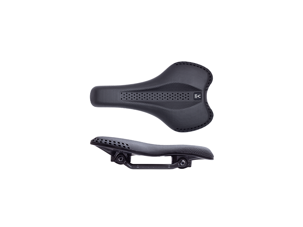
Loosen the saddle clamping bolts (T25) and remove the two clamping plates and the saddle.
Note: If you have a REVIVE valve adapter on hand, you can skip steps 2 to 4.

2.
Loosen and remove the grub screw (M3x0.5x3) of the lever-axle with a 1.5 mm Allen key and the grub screw (M4x0.7x5; non-drive side) of the lever with a 2 mm Allen key.

3.
Now remove the lever and the lever-axle.

4.
Remove the valve cap.
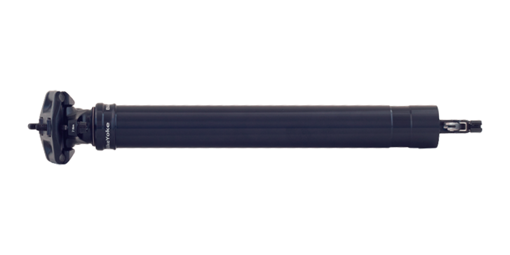
IMPORTANT: Make sure that the dropper is upright and fully extended before you connect a shock pump.
TIP: Use the REVIVE valve-adapter for easier attachment of the pump.

5.
Screw on the shock pump and completely deflate the seatpost.
NOTE: Occasionally actuate the actuator lever on the foot of the dropper during deflation so that the pressure can be fully released.

6.
Turn the seat post with its foot upwards and fix it with a suitable tool to make it easier to remove the circlip (DIN472 R28). Then remove the circlip from the seat in the lower tube.
Tool recommendation: Knipex 48 21 J21 19-60 mm for inner rings

7.
Slide the lower tube all the way towards the dropper head and loosen the foot from the piston rod by turning it anti-clockwise using a suitable 7 mm and 13 mm open-end spanner.
Tool tip: Knipex pliers spanner 86 03 125 and 86 03 180

8.
Remove the actuator rod, the foam ring and the bottom-out-bumper.

9.
Now loosen the circlip (DIN471 S12) from the lower bushing.
TIP: To protect the piston rod from damage, we recommend taping the area that the pliers may come into contact with. The lower tube can then be removed.
Tool recommendation: Knipex 49 21 A11 10-25 mm for outer rings

10.
Remove the lower bushing, the 6 guiding pins and the wiper from the lower tube.
NOTE: If a blue bushing is installed, it should not be reinstalled, but replaced with a new grey bushing, which is included in service kit #3.1.

11.
Clean all parts thoroughly with a soft cloth and isopropanol to remove dirt, grease residues and moisture.
NOTE: If parts are defective or worn, they should be replaced with new ones. All common parts that should be replaced during this service are included in our service kits.

12.
Loosen the seal head depending on the version with a 10 mm open-end spanner or a suitable face spanner.
TIP: Instead of a face spanner a suitable circlip pliers (e.g. Knipex 49 21 A11 10-25 mm) can be used.
Tool recommendation: Park Tool SPA-2

13.
Remove the seal head and the piston rod together with the main piston from the upper tube of the seat post and pour out the oil inside the tube.
IMPORTANT: In case of a REVIVE with Microvalve (this is the rule), a major part of the oil remains in the upper tube. The remaining oil should be drained in the next step. Therefore, a suitable container should be placed underneath before the inner tube is removed together with the Microvalve.

14.
Secure the upper tube with a suitable tool and press the reset unit together with the inner tube out of the upper tube. A suitable piece of plastic or wood can be used for easier disassembly.
CAUTION: Since oil can leak out, place an oil drip tray underneath.

15.
Loosen the reset unit from the inner tube and remove the Microvalve from the inner tube.
NOTE: The Microvalve is not used with older REVIVE generations.

16.
Remove the o-rings from the reset unit.
O-rings (NBR70): 2x1.5, 8x2,11.5x2 (13x2 on old Reset units, Revive 1st generation)

17.
Remove the O-rings and the backup ring (white) from the main piston.
O-rings: 7x2.5 NBR70, 2x1.5 NBR90

18.
Remove the o-ring and the u-cup (blue) in the seal head.
O-rings: 17x2 NBR70, u-cup

19.
Heat the main piston before unscrewing the piston rod with a 7 mm open-end spanner.
TIP: Since the o-ring (2.5x1.5 NBR70) inside the main piston, on the valve needle, does usually not wear out, this step can be skipped.
However, the main piston should then be checked for correct and firm seating on the piston rod.

20.
Remove the valve needle from the main piston and remove the o-ring.
O-ring: 2.5x1.5 NBR70
NOTE: A spring is not used on all models and may therefore be missing. The spring has no influence on the function of the seatpost and does not have to be installed.

21.
Clean all parts thoroughly with a soft cloth and isopropanol and remove dirt, oil and grease residues.

22.
Fit and grease the o-rings on the valve needle and put it back into the main piston.
O-rings: 2.5x1.5 NBR70, 2x1.5 NBR90

23.
Degrease the thread of the piston rod and apply a small amount of medium-strength threadlocker to the thread before screwing it back onto the main piston using a 7 mm open-end spanner (6 Nm).

24.
Now insert the u-cup into the seal head.
NOTE: The u-cup has two different sides, make sure that it is installed the right way round.

25.
Attach the O-ring to the seal head and press it carefully over the piston rod.
O-ring: 17x2 NBR70
NOTE: Be very careful when mounting the seal head to avoid damaging the u-cup when sliding it over the piston rod.

26.
Fit the backup ring (white) and the o-ring onto the main piston and grease the o-rings on the main piston and the seal head.
O-rings: 7x2.5 NBR70, backup ring

27.
Fit and grease the o-rings on the reset unit.
O-rings (NBR70): 2x1.5, 8x2, 11.5x2 (13x2 on old Reset units, Revive 1st generation)

28.
Place the reset unit back into the upper tube, bring it into position and press it back into the seat using a suitable tool until you hear a clicking noise.

29.
Fit the Microvalve onto the inner tube.
NOTE: The Microvalve has two different sides, make sure that it is installed the right way round.

30.
Fill the upper tube with the specified amount of oil and reinsert the inner tube into the upper tube.

31.
Position the inner tube and carefully push it back into its seat until you hear a clicking noise.

32.
Now guide the main piston back into the inner tube and screw the seal head back onto the upper tube (4 Nm). Depending on the design of the seal head, a 10 mm open-end spanner or face spanner must be used for this.
TIP: Instead of a face spanner a suitable circlip pliers (e.g. Knipex 49 21 A11 10-25 mm) can be used.
Tool recommendation: Park Tool SPA-2

33.
Grease the seat of the wiper with appropriate suspension grease and put it back in place. Then also grease the inside of the wiper.
TIP: Appropriate greases are, for example, BikeYoke Dropper Goo, Buzzy's Slick Honey, Rock Shox Dynamic Grease and R.S.P. Slick Kick

34.
IMPORTANT: Grease the seats of the guiding pins on the upper tube and the milling grooves inside the lower tube. Then carefully slip the lower tube over the upper tube with the wiper facing forwards and push it all the way onto the upper tube.
TIP: For easier installation and to avoid damaging the wiper, the lower tube should be slid over the upper tube with a careful tilting movement.

35.
Now insert the 6 guiding pins fully into the intended positions between the upper and lower tube.
TIP: Turn the lower tube until the pins can be inserted without much resistance. The actuator rod can also be used as a tool to push the pins into place as far as possible.

36.
Place the lower bushing over the piston rod and press it fully onto the seal head until the seat for the circlip (DIN471 S12) is fully exposed.

37.
Slide the circlip (DIN471 S12) onto the piston rod.
TIP: To avoid damaging the piston rod, we recommend simply letting the retaining ring drop down as shown in the picture.
NOTE: Circlips usually have one side with sharp edges and one side with rounded edges. In this case, the side with the sharp edge should point towards the foot unit.

38.
Secure the lower bushing with the circlip (DIN471 S12) and ensure that the circlip is correctly and fully seated.
NOTE: Twist the circlip with one of the pins of the circlip pliers to check again that it is correctly and fully seated.
TIP: To protect the piston rod from damage, we recommend taping the area that the pliers may come into contact with.
Tool recommendation: Knipex 49 21 A11 10-25 mm for outer rings

39.
Slide the bottom-out-bumper and then the foam ring onto the piston rod.

40.
Push the lightly greased actuator rod back into the piston rod and clean the thread of the piston rod thoroughly with isopropanol and remove all grease residues.

41.
Apply some medium-strength threadlocker (Loctite) to the thread of the piston rod before screwing on the foot unit again.

42.
Use a suitable 7 mm and 13 mm open-end spanner and tighten the foot (clockwise) back onto the piston rod. We specify a maximum torque of 4.5 Nm (hand-tight).
Tool tip: Knipex pliers spanner 86 03 125 and 86 03 180

43.
Push the bottom-out-bumper and the foam ring into the lower tube and then pull the lower tube all the way up until the foot unit fully engages.

44.
Replace the circlip (DIN472 R28) in the lower tube and ensure that the circlip is seated correctly and completely.
NOTE: Circlips usually have one side with sharp edges and one side with rounded edges. In this case, the side with the sharp edge should point towards the foot unit.
Tool recommendation: Knipex 48 21 J21 19-60 mm for inner rings

45.
Twist the circlip with one of the pins of the circlip pliers to check again that it is correctly and fully seated.

46.
Put the lever axle and the lever for the reset back into the prop head and fasten them with the grub screws M3x0.5x3 (1.5 mm Allen key) and M4x0.7x5 (2 mm Allen key).
NOTE: The M3 screw is only used to secure the lever axle against falling out and should only be tightened so firmly that the axle can still be turned.
47.
Bring the seatpost into an upright position, screw on the shock pump together with the valve adapter and set a pressure between 250 and 300 psi. Then replace the valve cap on the valve.
TIP: While pumping up the dropper, occasionally actuate the actuator lever at the foot of the seatpost to equalise pressure.
