


full service DIVINE

1.
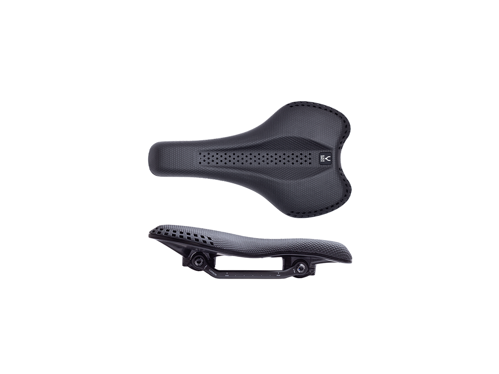
Loosen the saddle clamping bolts (T25) and remove the two clamping plates and the saddle.

2.
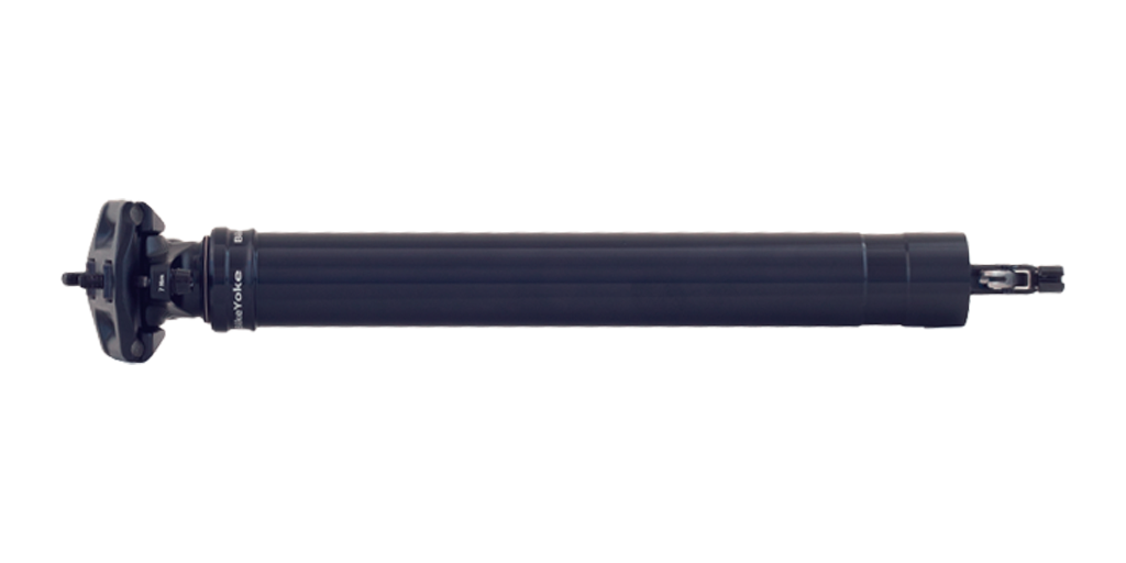
Remove the valve cap. Make sure that the dropper is fully extended and upright. Then screw on a shock pump and use it to completely release the pressure.

3.
Turn the seatpost so that the foot is pointing upwards and secure the seatpost with a suitable tool for further disassembly.

4.
Remove the locking ring (DIN 472 R 28) from its seat in the lower tube.
Recommended tool: Knipex 48 21 J21 19–60 mm for inner rings.

5.
Slide the lower tube all the way towards the dropper head and loosen the foot from the piston rod by turning it anti-clockwise using a suitable 7 mm and 13 mm open-end spanner.
Tool tip: Knipex pliers spanner 86 03 125 and 86 03 180

6.
Remove the actuator (push) rod, the foam ring and the bottom-out-bumper.

7.
Now loosen the circlip (DIN471 S12) from the lower bushing.
TIP: To protect the piston rod from damage, we recommend taping the area that the pliers may come into contact with. The lower tube can then be removed.
Tool recommendation: Knipex 49 21 A11 10-25 mm for outer rings

8.
Remove the lower bushing, the 6 guiding pins and the wiper from the lower tube.
NOTE: If a blue bushing is installed, it should not be reinstalled, but replaced with a new grey bushing, which is included in service kit #3.1.

9.
Clean all parts thoroughly with a soft cloth and isopropanol to remove dirt, grease residues and moisture.
NOTE: If parts are defective or worn, they should be replaced with new ones. All common parts that should be replaced during this service are included in our service kits.

10.
Loosen the seal head depending on the version with a 10 mm open-end spanner or a suitable face spanner.
TIP: Instead of a face spanner a suitable circlip pliers (e.g. Knipex 49 21 A11 10-25 mm) can be used.
Tool recommendation: Park Tool SPA-2

11.
Remove the seal head and the piston rod together with the main piston from the upper tube of the seat post and pour out the oil inside the tube.

12.
Remove the o-ring on the main piston.
O-ring: 16x2.5 NBR70

13.
Remove the o-ring and the u-cup (blue) in the seal head.
O-rings: 17x2 NBR70, u-cup

14.
Use the actuator rod to push the main valve upwards and remove the small o-ring.
O-ring: 2.5 x 1.5 NBR70

15.
The o-ring on the main valve can now be replaced with a new one.
O-ring: 2.5 x 1.5 NBR70

16.
Heat the main piston before unscrewing the piston rod with a 7 mm open-end wrench.
TIP: Since the O-ring (2.5x1.5 or 2.5x1) inside the main piston, on the main valve, does not usually wear out, steps 16 to 19 can be omitted.
However, the main piston should be checked to ensure that it is correctly and securely seated on the piston rod.

17.
Remove the main valve from the main piston/piston rod and remove the O-rings.
O-rings:
DIVINE: 2 x 2.5x1.5 NBR70
DIVINE 2.0: 1 x 2.5x1.5 NBR70 and 1 x 2.5x1 NBR70

18.
Fit the O-rings onto the main valve, grease them, and then put the main valve back into the piston rod.

19.
Degrease the thread of the piston rod and apply a small amount of medium-strength threadlocker to the thread before screwing it back onto the main piston using a 7 mm open-end wrench (6 Nm).

20.
Use a bit of grease to fit the O-ring onto the main piston.
O-ring: 16x2.5 NBR70

21.
Now insert the U-cup into the seal head.
NOTE: Since the U-cup has two sides, make sure that it is installed the right way round.

22.
Attach the O-ring to the seal head and carefully slide it over the piston rod.
Note: Be careful when installing the seal head to avoid damaging the U-cup when sliding it over the piston rod.
O-ring: 17x2 NBR 70

23.
Fill the upper tube with the specified amount of oil. Find information here.

24.
Ensure that the O-rings on the seal head and main piston are greased, and place the unit back into the upper tube. Then tighten the seal head to 4 Nm.
Depending on the design of the seal head, a 10 mm open-end wrench or face spanner must be used for this purpose.
TIP: Instead of a face wrench, you can also use suitable circlip pliers (e.g., Knipex 49 21 A11 10-25 mm).
Tool recommendation: Park Tool SPA-2

25.
Grease the wiper seat with suitable suspension grease and put it back in place. Then grease the inside of the wiper as well.
TIP: Suitable greases include BikeYoke Dropper Goo, Buzzy's Slick Honey, Rock Shox Dynamic Grease, and R.S.P. Slick Kick.

26.
IMPORTANT: Lubricate the guide pin seats on the upper tube and the milling grooves inside the lower tube with sufficient grease. Then carefully place the lower tube with the wiper facing forward over the upper tube and push it all the way onto the upper tube until it stops.
TIP: For easier installation and to avoid damage to the wiper, it should be pushed over the lower tube with a careful tilting movement.

27.
Now insert the 6 guide pins completely into the designated positions between the upper and lower tubes.
TIP: Turn the lower tube until the pins can be inserted without much resistance. The actuator rod can be used as a tool to push the pins in as far as possible.

28.
Thread the lower bushing onto the piston rod and press it completely onto the seal head until the seat for the retaining ring (DIN471 S12) is exposed.

29.
FNow thread the circlip (DIN471 S12) onto the piston rod.
TIP: To avoid damaging the piston rod, we recommend simply letting the circlip fall down as shown in the picture.

30.
Secure the lower bushing with the circlip (DIN471 S12) and ensure that the circlip is correctly and fully seated.
NOTE: Turn the circlip with one of the pins of the circlip pliers to check once again that it is correctly and fully seated.
TIP: To protect the piston rod from damage, we recommend covering the area that may come into contact with the pliers with adhesive tape.
Recommended tool: Knipex 49 21 A11 10-25 mm for outer rings

31.
Now thread the bottom-out bumper and then the foam ring onto the piston rod.

32.
Slide the lightly greased actuator rod back into the piston rod, thoroughly clean the thread of the piston rod with isopropanol, and remove all grease residue.

33.
Apply some medium-strength threadlocker (e.g., Loctite) to the thread of the piston rod before screwing the foot back on.

34.
Use a suitable 7 mm and 13 mm open-end wrench and screw the foot back onto the piston rod (clockwise). We specify a maximum torque of 4.5 Nm (hand-tight).
Tool tip: Knipex pliers wrench 86 03 125 and 86 03 180

35.
Press the bottom-out bumper and the foam ring slightly into the lower tube and then push the lower tube toward the foot of the seatpost until it clicks into place.

36.
Reinsert the circlip (DIN472 R28) into the lower tube and ensure that the circlip is correctly and fully seated.
NOTE: This Circlip has one side with sharp edges and one side with rounded edges. In this case, the side with the sharp edge should face towards the outside.
Recommended tool: Knipex 48 21 J21 19-60 mm for inner rings

37.
Turn the circlip with one of the pins on the circlip pliers to check once again that it is correctly and fully seated.

38.
Put the seatpost in an upright position and screw on the shock pump. Inflate the post to a pressure of around 100 psi, then fully extend it by operating the lever on the foot before increasing the pressure to between 350 and a maximum of 400 psi. Then screw the valve cap back onto the valve.
